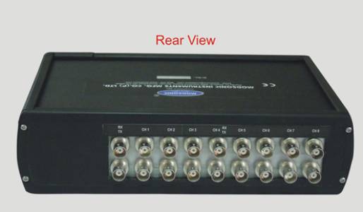
Multiplexer

      Rs

      Description


      Multiplexer: Selectively Route Signals

      A multiplexer (MUX), also known as a data selector, is a combinational logic circuit that selects one of several input signals and forwards the selected input to a single output line. Think of it as a sophisticated switch that directs traffic based on a control signal. This allows for efficient use of resources and enables complex signal routing within larger systems.

      Key Features and Specifications:

      • Input Channels: Available in various configurations, ranging from 2:1 (2 inputs, 1 output) to significantly larger configurations like 8:1, 16:1, or even higher, depending on the specific model and application. The number of inputs is often represented as N in an N:1 multiplexer.
      • Select Lines: These control lines (often denoted as S0, S1, etc.) determine which input signal is passed to the output. The number of select lines determines the maximum number of inputs that can be handled (2number of select lines = number of inputs). For example, a 4:1 multiplexer needs 2 select lines (2² = 4).
      • Output Line: A single output line carries the selected input signal.
      • Logic Functionality: The multiplexer operates based on Boolean logic. Each input is connected to the output through a logic gate (typically AND gates) controlled by the select lines.
      • Technology: Multiplexers are available in various technologies including TTL (Transistor-Transistor Logic), CMOS (Complementary Metal-Oxidesemiconductor), and integrated circuit (IC) forms. These technologies impact speed, power consumption, and noise immunity.
      • Applications: Multiplexers find extensive use in:
        • Data Communication: Routing data streams from multiple sources onto a single communication line.
        • Digital Signal Processing (DSP): Selecting different input signals for processing.
        • Computer Architecture: Addressing memory locations, selecting peripherals, and implementing memory banks.
        • Telecommunications: Switching signals in telephone systems and other communication networks.
        • Testing and Measurement: Selecting signals for monitoring and analysis.

      Selecting the Right Multiplexer:

      Choosing the correct multiplexer depends on several factors:

      • Number of Inputs: Determine the required number of input channels based on your application's needs.
      • Logic Family: Select a logic family (TTL, CMOS, etc.) compatible with the surrounding circuitry.
      • Voltage and Current Requirements: Ensure compatibility with the power supply and load characteristics.
      • Speed: Consider the required switching speed and propagation delay.
      • Packaging: Choose the appropriate packaging (DIP, SOIC, QFP, etc.) based on space constraints and PCB design.

      Example: 4:1 Multiplexer Truth Table

      A 4:1 multiplexer would have a truth table like this:

      S1S0I3I2I1I0Output
      00XXXI0I0
      01XXI1XI1
      10XI2XXI2
      11I3XXXI3

      Where 'X' denotes a 'don't care' condition (the input value doesn't affect the output).

      This detailed description provides a comprehensive understanding of multiplexers, their functionalities, and considerations for selecting the appropriate component for a specific application. Remember to consult datasheets for specific model details.

      Seller Details

      Modsonic Instruments Manufacturing Co (P) Ltd : Ultrasonic Flaw Detector Manufacturer

      Ahmadabad, gujarat

      ["Suppliers"]

      Looking for Best Price

      Tags: Multiplexer